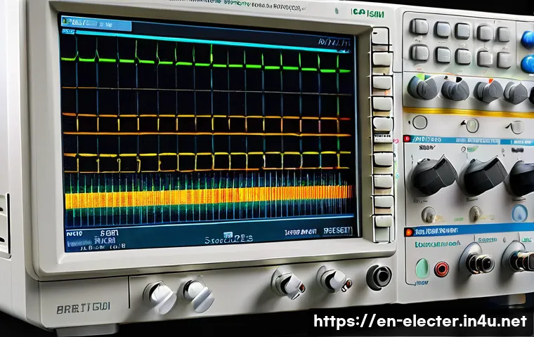
Mastering the oscilloscope is a game-changer for anyone working with electronics or signal analysis. This essential tool allows you to visualize electrical signals, making troubleshooting and design much more intuitive.
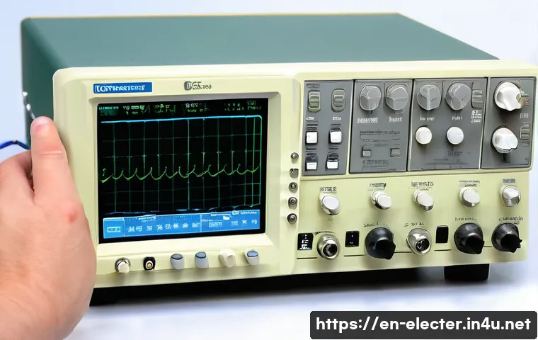
Whether you’re a beginner or looking to refine your skills, understanding how to properly use an oscilloscope can save you hours of guesswork. From setting up probes to interpreting waveforms, getting comfortable with this device opens up a new world of precision.
Let’s dive into the details and explore how to make the most out of your oscilloscope!
Getting Comfortable with Your Oscilloscope Setup
Choosing and Connecting the Right Probes
When I first started using an oscilloscope, one of the trickiest parts was figuring out which probe to use. The probe type can drastically affect your readings.
For most general-purpose measurements, a 10x passive probe is a solid choice because it offers a good balance between signal integrity and input impedance.
Connecting the probe properly is just as important—make sure the ground clip is securely attached to the circuit’s ground reference. A loose or improper ground connection often leads to noisy signals or inaccurate measurements.
I’ve learned that taking a moment to double-check probe connections before powering on saves loads of headache later.
Adjusting Vertical and Horizontal Controls
Mastering vertical and horizontal adjustments is essential for getting a clear view of your waveform. The vertical scale controls the signal amplitude display, while the horizontal scale adjusts the time base.
When you’re dealing with fast signals, I found that slowing down the horizontal sweep lets you zoom in on waveform details, making subtle glitches easier to spot.
Conversely, for slower signals, speeding up the time base can help capture the full waveform cycle. Don’t forget to tweak the vertical position to center your waveform vertically on the screen—this makes reading voltage levels way simpler and less stressful.
Triggering to Stabilize Your Signal
Triggering is like the heartbeat of oscilloscope measurements. Without a proper trigger setup, your waveform will appear unstable or jump around, making analysis nearly impossible.
The trigger level sets the voltage point at which the oscilloscope starts capturing data, so adjusting this carefully is crucial. I often use edge triggering, where the oscilloscope triggers on a rising or falling edge of the signal.
This keeps the waveform steady and synchronized. Experimenting with trigger modes and levels until the waveform locks in place is a game-changer for quick, reliable readings.
Decoding Waveforms and Signal Characteristics
Identifying Signal Types by Shape
Learning to recognize different waveform shapes is a skill that drastically improves your troubleshooting speed. Sine waves typically indicate AC signals or oscillators, while square waves are common in digital circuits.
When I first noticed a distorted sine wave on my scope, it pointed me straight to a power supply issue. Triangular and sawtooth waves often appear in timing circuits or audio synthesis.
Understanding these shapes helps you immediately infer what part of your circuit might be misbehaving or working as expected.
Measuring Amplitude and Frequency Precisely
Amplitude and frequency are the core parameters you’ll analyze on an oscilloscope. Amplitude measurement involves reading the peak-to-peak voltage, which tells you how strong your signal is.
Frequency, the number of cycles per second, is crucial for timing and synchronization tasks. I use the scope’s cursors or built-in measurement tools to get precise values.
This is especially helpful when working with complex or noisy signals where eyeballing the waveform just isn’t accurate enough. Over time, relying on these tools has saved me countless hours of guesswork.
Spotting Noise and Interference
Noise can be a silent killer in your circuit analysis. Sometimes, a waveform might look “off” without any obvious reason, and that’s where your scope’s ability to reveal noise comes in handy.
Using bandwidth limiting features and proper probe grounding reduces noise pickup. I often enable the averaging function to smooth out random noise and get a clearer picture of the underlying signal.
Recognizing the difference between actual signal anomalies and noise helps you avoid chasing phantom problems.
Advanced Techniques to Enhance Signal Analysis
Utilizing Math Functions for Deeper Insight
Modern oscilloscopes come packed with math functions that let you perform real-time calculations on your signals. Functions like addition, subtraction, and FFT (Fast Fourier Transform) can reveal frequency components or compare two signals directly.
I found using FFT analysis particularly eye-opening when trying to identify harmonic distortion in audio circuits. While it might seem intimidating at first, playing around with these features unlocks a whole new level of signal understanding.
Leveraging Persistence and Storage Modes
Persistence mode is a lifesaver when you want to observe how signals change over time, especially for irregular or bursty signals. It overlays multiple waveform captures, highlighting variations and anomalies.
Storage mode, on the other hand, allows you to freeze a waveform for detailed analysis or documentation. I regularly save waveforms to USB or internal memory to compare before-and-after measurements when tweaking circuits.
These modes make your oscilloscope feel less like a snapshot tool and more like a dynamic diagnostic assistant.
Interfacing with PC Software for Extended Analysis
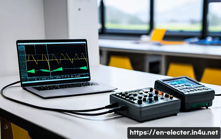
Connecting your oscilloscope to a PC expands its capabilities exponentially. Many scopes offer USB or Ethernet interfaces to stream data directly into analysis software.
I’ve used this feature to log long-term signal data and create detailed reports, which is invaluable for professional troubleshooting or design verification.
The ability to zoom, annotate, and compare waveforms on a larger screen makes complex analysis much less daunting. Plus, sharing these files with colleagues speeds up collaboration and problem-solving.
Essential Calibration and Maintenance Tips
Regular Calibration for Accurate Readings
Keeping your oscilloscope calibrated is critical to maintain measurement accuracy. Most manufacturers recommend annual calibration by authorized service centers, but you can also perform basic checks yourself.
For example, using the built-in calibration signal output to verify probe compensation is a quick routine I do before any serious measurement session.
Neglecting calibration can lead to subtle errors that compound over time, turning your trusted tool into a source of confusion.
Cleaning and Caring for Your Equipment
An oscilloscope is an investment, and treating it well prolongs its lifespan. Dust and grime can accumulate on the screen, knobs, and connectors, affecting usability and signal quality.
I keep a microfiber cloth handy for gentle cleaning and avoid harsh chemicals that might damage the screen coating. Also, storing probes properly to prevent cable damage is something I wish I’d done from day one.
Simple maintenance habits prevent unexpected failures and keep your scope ready whenever you need it.
Handling Probes and Cables with Care
Probes and cables are often the first components to wear out, but their condition directly impacts your measurements. Avoid bending cables sharply or pulling on connectors, as these actions can cause internal breaks.
I once spent hours chasing a phantom noise only to discover a damaged probe tip was the culprit. Regularly inspecting and replacing worn probes is a small time investment that pays off with reliable data and less frustration.
Common Mistakes and How to Avoid Them
Misinterpreting Ground References
One of the most frequent errors I see—especially with beginners—is incorrect grounding. If the probe ground clip isn’t connected to the circuit’s true ground, the displayed waveform can be misleading or noisy.
Sometimes, people ground to the wrong point or forget the clip altogether, resulting in floating signals that don’t represent reality. Taking a moment to confirm your ground reference can save hours of wasted troubleshooting and prevent potential damage to your device or circuit.
Overloading Input Channels
Applying a voltage that exceeds the oscilloscope’s input rating can damage the device or distort measurements. I’ve accidentally connected probes to high-voltage points without checking limits, instantly frying a channel.
Always verify your oscilloscope’s maximum input voltage and use appropriate attenuators or probes designed for higher voltages. This cautionary step is essential when working with power electronics or industrial equipment.
Ignoring Probe Compensation
Proper probe compensation ensures the probe’s frequency response matches the oscilloscope’s input, resulting in accurate waveform shapes. If the compensation is off, square waves can look rounded or distorted.
I recommend adjusting probe compensation using the oscilloscope’s built-in calibration signal before each measurement session. It’s a quick step that often gets overlooked but makes a noticeable difference in signal fidelity.
Comparing Popular Oscilloscope Types and Features
Analog vs. Digital Oscilloscopes
Analog oscilloscopes display waveforms directly using cathode ray tubes, offering real-time, continuous signals but limited storage and analysis features.
Digital oscilloscopes convert signals into digital data, providing advanced functions like storage, math operations, and connectivity. From my experience, digital scopes are more versatile for modern electronics work, but analog scopes still have their charm for simple, fast visual feedback.
Handheld vs. Benchtop Models
Handheld oscilloscopes offer portability and convenience for fieldwork, making them perfect for on-site troubleshooting. However, they often trade off screen size, bandwidth, and feature richness compared to benchtop models.
Benchtop oscilloscopes are ideal for detailed lab work, providing larger displays, more channels, and higher performance. Choosing between them depends on your specific use case and budget.
Key Features to Prioritize When Buying
When shopping for an oscilloscope, several features should guide your choice: bandwidth, sample rate, number of channels, memory depth, and connectivity options.
Bandwidth should be at least five times higher than your highest signal frequency for accurate capture. Higher sample rates improve waveform detail, while more channels allow simultaneous multi-point analysis.
Memory depth affects how long signals can be stored, and connectivity enables PC integration. The table below summarizes these key specs and why they matter.
| Feature | Importance | Recommended Value |
|---|---|---|
| Bandwidth | Determines max frequency captured accurately | ≥ 5x highest signal frequency |
| Sample Rate | Resolution of signal details | ≥ 2x bandwidth |
| Channels | Number of simultaneous signals observed | 2 or more depending on complexity |
| Memory Depth | Length of waveform stored | Deeper memory for longer captures |
| Connectivity | Data transfer and remote control | USB, Ethernet, or Wi-Fi preferred |
Conclusion
Getting comfortable with your oscilloscope takes practice, but mastering the basics unlocks a world of possibilities in signal analysis. With the right setup and understanding, you can confidently troubleshoot, measure, and interpret complex waveforms. Remember, each step you take builds your skill and makes your work more efficient and accurate. Keep exploring advanced features to deepen your insights and make the most of this invaluable tool.
Useful Tips to Remember
1. Always double-check your probe connections and ground references before starting measurements to avoid noisy or misleading signals.
2. Use vertical and horizontal controls thoughtfully to zoom in on waveform details or view full signal cycles for better clarity.
3. Take advantage of your oscilloscope’s math and persistence functions to reveal hidden signal characteristics and changes over time.
4. Regularly calibrate your oscilloscope and maintain your probes and cables to ensure consistent accuracy and reliability.
5. Choose an oscilloscope with the right bandwidth, sample rate, and connectivity options that match your specific needs for best performance.
Key Takeaways
Proper setup and understanding of your oscilloscope are essential for accurate and effective signal analysis. Grounding errors and probe mismanagement are common pitfalls that can compromise results. Embracing advanced features like math functions and PC interfacing enhances diagnostic capabilities. Regular calibration and careful equipment maintenance protect your investment and ensure measurement precision. Finally, selecting an oscilloscope tailored to your application’s demands will maximize your productivity and troubleshooting success.
Frequently Asked Questions (FAQ) 📖
Q: What is the best way to connect probes to an oscilloscope for accurate measurements?
A: The key to accurate measurements starts with properly connecting your probes. Always use the oscilloscope’s designated probe inputs and ensure the ground clip is securely attached to the circuit’s ground reference point.
Avoid long ground leads, as they can introduce noise and distort the signal. I found that using a short, direct ground connection significantly improves waveform clarity.
Also, make sure your probes are correctly compensated; many oscilloscopes have a built-in square wave test signal to adjust the probe compensation for the most accurate display.
Q: How do I interpret different waveform shapes on the oscilloscope?
A: Understanding waveform shapes takes some practice but is vital for troubleshooting and design. A clean sine wave usually indicates a stable AC signal, while square waves often represent digital signals or clock pulses.
If you see distorted, noisy, or clipped waveforms, it could suggest issues like signal interference, improper voltage levels, or faulty components. When I first started, I kept a reference chart handy and matched waveforms to common signal types, which really helped me identify problems faster.
Over time, you’ll develop an intuition for what normal and abnormal signals look like.
Q: What are some common mistakes beginners make when using an oscilloscope?
A: Beginners often rush setup, leading to inaccurate readings. One common mistake is not properly setting the vertical and horizontal scales, which can either compress or stretch the waveform and hide important details.
Another is neglecting to check probe compensation, resulting in distorted signals. Also, many overlook the importance of triggering settings; without correct triggering, the waveform won’t stabilize on the screen, making analysis frustrating.
From my experience, taking a moment to carefully adjust these settings before diving into measurement saves a lot of time and confusion.